Heat is Energy – Particles in Motion
There are only 6 basic parts to the modern refrigerator. They work together to create the ‘cold’ using a few physical principles.
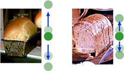
What we experience as heat, is best understood as the rate of vibration, or energy level, of the fundamental particles of matter (atoms or molecules).
All matter is composed of sub microscopic particles called molecules (or in elemental materials, atoms) and normally in motion.
In a solid, these minute particles are strongly attracted to each other and so can’t move very far. Each one tends to vibrate back and forth around a fixed position. The faster they vibrate, the warmer the solid feels to the touch.
When a solid is warmed up it can melt and become liquid. In a liquid, the sub microscopic particles are vibrating so energetically they overcome some of the forces that attract them to each other. They can slip around, changing places with each other.
When a liquid is warmed still farther, it can evaporate and become a gas. In the gas, the sub microscopic particles completely lose touch with each other and travel freely. They no longer vibrate around fixed positions but begin to travel around in erratic, independent paths.
Whether in a solid, a liquid or in a gas, the hotter the material, the faster is the motion of the particles of matter.
Expanding Gas Absorbs Heat Energy
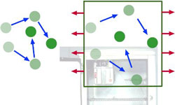
Gas particles move rapidly at high temperatures. As a gas expands, its molecules slow down, it cools off, and is able to absorb heat energy from its environment.
Nineteenth century physicists discovered that when a gas is allowed to expand, its temperature drops. The particle motion theory of heat explains this by following the motion of a gas particle that hits the wall of a container and bounces off. If the container wall is still, the particle bounces back at the same velocity with which it hit the wall.
But if the wall is moving away (as is the case when the chamber containing the gas is expanding), some of the particle’s energy is transferred to the wall and the particle bounces back at a slower velocity than it had before. As the particles of the gas slow down, the gas becomes cooler.
By the principle of conduction, matter at a lower temperature can absorb energy from matter at a higher temperature. In the process, the first substance is warmed up (its particles start to move faster) and the second is cooled down as its particles lose energy and begin to move more slowly.
Energy is Expended in Compressing a Gas
To prepare a gas for refrigeration, electrical energy is used to compress it.
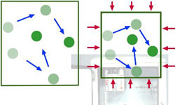
Those same nineteenth century physicists also observed that if a gas is compressed it heats up. Gas particles rebounding off the advancing walls of a chamber that is getting smaller absorb some of the wall’s energy of motion and travel faster than before. The faster moving gas particles have more energy and a warmer temperature.
But it’s not easy to compress a gas. Work has to be done and energy expended to force the gas into an ever smaller and smaller space. At least part of the energy expended in the compression process is transformed into heat energy stored in the compressed gas.
Gases used refrigerant in household refrigerators are capable of being compressed and liquefied under only moderate pressure. This key component of the mechanical refrigeration process is usually referred to as a refrigerant rather than a gas because it changes back and forth between gaseous and liquid states as it moves through the system.
Manipulating Environmental Temperature Using a Compressible Gas
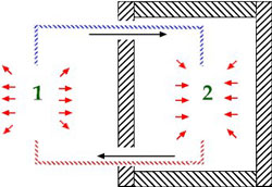
If you can compress gas in one space and then let it expand in a second, isolated space, you can control local temperature. You ‘pump’ heat from one space to another.
Gas can be cooled down by letting it transfer energy by conduction to its environment. When enough heat has been removed, the gas molecules are moving so slowly that they once again begin to be attracted strongly to each other. Eventually the particles ‘stick together’ and the gas condenses. It is transformed back into the liquid state.
So by removing energy, the gas is condensed. If the resulting liquid is later allowed to absorb heat energy from its environment, it will evaporate again. It will be transformed back to the gaseous state.
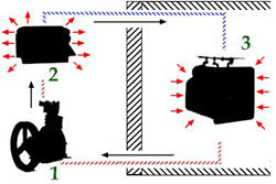
These discoveries about the properties of a gas undergoing compression, cooling and evaporation led eventually to the development of equipment for mechanical refrigeration. If a refrigerant gas is first compressed by the expenditure of energy and then its heat is released to the environment, it can subsequently be carried into an insulated space and be allowed to evaporate. The evaporating liquid cools the insulated space and the resulting gas is then passed back to the compressor where the cycle is repeated.
The result of this process is that heat absorbed in the insulated chamber is carried away and released to the surrounding environment during the condensation phase. Heat has been pumped out of the insulated container and into the environment. Anything stored in the chamber will be cooled off in the process.
Early Refrigeration Machinery
Mechanical refrigeration makes use of several different devices to alternately compress and liquefy a gas and then let it expand again.
The reciprocating compressor is a device with an internal piston that is used to force gas trapped in a cylinder to occupy a smaller volume. The work done by the rapidly moving piston is what supplies the energy needed to compress the gas.
The condenser is a network of metal tubing, cooled by air, through which the hot compressed gas flows after leaving the compressor. This mechanism cools the gas and converts it to a liquid state.
The evaporator consists of a chamber and series of tubes into which the liquefied refrigerant is ejected through a flow control device, allowing it to expand, absorb heat from the environment and vaporize. The compressor (and its motor) and the condenser were placed together in a space that had to be well ventilated to dissipate the heat they generated. This equipment is referred to as the refrigeration machine.
The evaporator, or cooling unit, was placed in a separate, insulated space that was to be refrigerated. The contents of that space were cooled down by the evaporator’s operation.
Six Primary Components In The Refrigerator
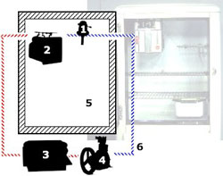
Six primary components were assembled in a single appliance to create the early, unitary household refrigerator.
The compressor and condenser liquefy the refrigerant gas and allow its heat to escape. The evaporator (with its flow control device) absorbs heat within an insulated compartment where food is stored.
Control of the system was provided by a temperature sensing device used to turn the compressor on and off. This thermostatic temperature control had a knob that could be used to adjust the set point of the thermostat to a higher or lower refrigeration temperature.
The evaporator, located inside the insulated food storage compartment was linked by copper tubing to the condenser and compressor. A food storage chamber with insulated walls served as the space that was kept cool and protected from heat in the environment.
A special refrigerant gas with the appropriate physical characteristics was circulated through sealed copper tubing by the action of the compressor. The refrigerant was cycled again and again between liquid and gaseous states by the actions of the various mechanical components.
Refining the Refrigerator Concept
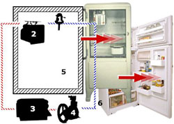
The first practical household refrigerator housed all six basic components in a single appliance. Since then the history of the refrigerator has consisted of improvements in each of the six components.
The engineering innovation that eventually put mechanical cooling in every home was the combination of six basic components in a single or unitary appliance, the household refrigerator.
The condenser, the compressor and its motor, comprising the ‘refrigeration machine,’ were all grouped together in a mechanical compartment at the bottom of the refrigerator.
The evaporator housed the freezing compartment for making ice and keeping ice cream. The whole thing was located inside the larger food storage compartment and served to cool it down. The thermostatic temperature control was normally attached to the evaporator.
The food storage chamber was a solidly constructed, metal-lined compartment with substantial insulation incorporated into the walls. Its walls were typically given a white porcelain finish. This was where the food was kept, and a large door permitted easy access by the householder.
This is the mechanical configuration that brought such benefits to the kitchens of small town Canada, and indeed to all of Canada. Public acceptance and refrigerator sales gave the manufacturers the needed capital to set out on decades of gradual improvements in all these components, right through until today.
Refrigerator Components: The Compressor
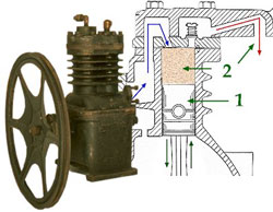
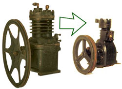
The reciprocating compressor used a motor-driven piston to compress the refrigerant gas.
Inside an early reciprocating compressor, the piston was forced up and down by a crank shaft powered by an electric motor. When the gas in the piston was compressed enough, a small valve at the top of the piston opened up to let it out. Then the piston went back down and a second valve opened to let new, uncompressed gas in to fill the cylinder.
The piston and cylinder mechanism was housed within a cast iron shell, strong enough to withstand the internal pressures. The cast iron housing often had exterior fins to permit increased contact with the air so that heat could be dissipated more effectively.
A large fly wheel was connected to the crank shaft that was attached to a connecting rod at the base of the piston. Turning the fly wheel turned the crank shaft and that transmitted motion to the connecting rod that alternately pushed the piston up and then pulled it down again.
All of the internal moving parts of the compressor were lubricated by an internal oil bath. The fly wheel was rotated by a circular belt connecting it to an electric motor.
Early reciprocating compressors were relatively large and inefficient, and operated at slow speeds. Operation produced an annoying amount of vibration and noise.
Improving the Compressor
Improvements in the reciprocating compressor made it smaller, faster, quieter and more energy efficient.
In order for the compressor to live up to the refrigerator’s billing as a ‘modern convenience,’ it had to be made to operate more quietly. It had to be converted from making what designer Raymond Loewy referred to as ‘an annoying buzz’ to running with a more comforting, quiet hum.
To accomplish this, compressors were designed to run faster, using new materials and improved engineering. Higher speed compressors were smaller, smoother and quieter.
The fly wheel was made smaller and better balanced so that it ran more quietly. The crank shaft was cleverly balanced with counter weights so that it ran with less vibration. And all parts were machined with higher precision so that they operated with less friction.
In time, demands for quieter machines and energy efficiency led to even smaller compressors running at higher speeds. Since the late 1930s the motor and compressor have been enclosed in a single ‘hermetic’ unit, so that the fly wheel and belt were no longer needed.
Refrigerator Components: The Evaporator
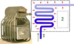
The evaporator allowed the compressed refrigerant to expand and absorb heat while passing through heat-exchange tubing.
The evaporator, located inside the food storage compartment was basically a device that allowed the incoming stream of liquefied refrigerant to expand into a network of metal tubes.
A lower pressure was created in the evaporator by an expansion valve and the suction created by the compressor. As a result, the refrigerant was able to expand, to absorb heat from its surroundings and to evaporate back to the gaseous state.
In early evaporators, the tubing was passed through a reservoir of brine solution, and the brine became very cold. The brine bath in turn surrounded the refrigerator’s freezing compartment and provided the constant function of cooling the compartment’s contents. Placing the entire evaporator in the food storage compartment meant that it absorbed heat from the air around it and created the cold environment necessary for the safe storage of perishable foods.
Improving The Evaporator
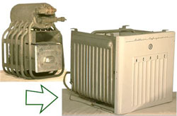
The earliest evaporators were large and cumbersome, but became more efficient with time.
There was little space for frozen foods in the earliest evaporators. Later models had more efficient heat-exchange tubing and a larger freezing compartment.
Advances in design to improve heat transfer and refrigerant flow control were a response to the market demand for larger cooling units. The result was a larger freezing unit. Now large items of food could be placed in the compartment as well as the ice cube trays that had originally been its sole inhabitants.
As freezer design evolved, many different types of valves were developed to control the flow of refrigerant into the evaporator. The better the flow was controlled, the more efficient the use that could be made of the evaporator’s heat transfer surfaces.
Some examples were float valves, automatic and thermostatic expansion valves, and capillary lines. The net result of these developments was a more efficient evaporator that offered greater utility to the householder.
Refrigerator Components: The Condenser
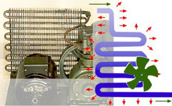
The early condenser consisted of heat exchange tubing cooled by a fan. Compressed gas passing through the tubing cooled and was converted to a liquid.
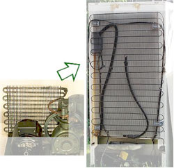
The condenser tubing could be fashioned either as a spiral or as a flattened series of U-shaped loops. As the gas passes through the tubing, it was cooled by the surrounding air.
This cooling effect was speeded up in early condensers by the use of metal heat-exchange fins on the outside of the tubing and by using a motor-driven fan to force a stream of cool air to flow over the tubing.
In the condenser tubing, the refrigerant gas was cooled so rapidly its molecules slowed down and began to adhere to each other. Eventually it condensed and traveled on to the evaporator in the liquid state. The condenser generated a lot of heat that had to be dissipated to ensure condensation of the refrigerant.
Improving The Condenser
Condensers for household cabinet refrigerators have become much quieter, operating without a fan.
By reducing the diameter of the condenser tubing and increasing its length, a greater external surface area was created. The total surface area of heat dissipation fins could be increased as well.
These changes offered a larger area over which contact with the surrounding air and heat exchange could take place by the processes of radiation and convection. With these improvements to condenser design, the efficiency of heat exchange was improved.
Eventually the condenser tubing was extended outside of the mechanical compartment at the base of the refrigerator and extended all the way up the back of the appliance. This put it in contact with a much larger volume of air.
Warm air rises, so the condenser tubing set up a convectional flow of rising warm air, flooding out at the top and being replaced by cooler air coming in at the bottom. This configuration was more energy efficient as well, as a motor driven fan was no longer needed.
Refrigerator Components: The Thermostat
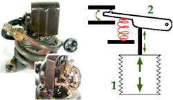
Early refrigerator thermostats employed a metal bellows to convert temperature fluctuations, through an elaborate assembly of levers and springs, to an electrical switch.
Control of the temperature level in the household refrigerator was accomplished by a thermostatic mechanism. The function of a thermostat, or temperature controlled switch, is to continuously monitor the internal temperature of the refrigerator to ensure that it doesn’t get either too hot or too cold.
In spite of its layer of insulation, the food storage compartment continuously experiences a slow loss of heat to the external environment. Early refrigerator thermostats sensed this heat loss as a stiff, metallic bellows slowly expanded.
When the bellows had expanded enough, it finally pushed a mechanical contact arm, through which it was attached by a series of springs and levers, up far enough so that it touched an electrical contact and completed a circuit that started the compressor motor.
As the compressor ran, the refrigeration process operated to slowly bring the temperature in the food chamber down again. The thermostat’s bellows began to contract and eventually pulled the mechanical contact arm down enough to break the electrical circuit and turn off the compressor motor. This combination of mechanical and electrical components is termed a feed-back system because information from the environment is fed back to the machinery which then operates to keep the environment constant.
Improving The Thermostat
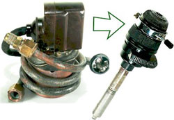
The incorporation of improved heat sensing materials and electrical switching eventually allowed thermostats to become more compact and offer better temperature control.
Some early thermostatic controls had the target refrigeration temperature, called the set point, built in to the system. Only a refrigerator repair technician could adjust this temperature at which the food was maintained.
An early improvement was to add an external control that could be operated by the householder. A rotating knob made it possible to adjust the set point, the target temperature for food storage, either higher or lower.
Controls eventually became increasingly sophisticated. A switch was added to allow the homemaker to defrost the freezer compartment and an overload switch protected the compressor motor. At the same time the thermostatic control was being made smaller and more sensitive by replacing the bulky bellows with a smaller, faster-acting capillary line sensor.
Refrigerator Components: The Cabinet
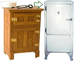
The refrigerator cabinet is just an insulated box, designed in the first household refrigerators, to be similar in appearance to an ice box.
The first refrigerator cabinets simply took the general appearance of the ice box and added gleaming white exterior. The enamelled or porcelain steel exterior panels sheathed a wooden frame and layers of cork insulation.
Similar hardware was used for the door latch and hinges. Even the ice box legs were retained, although the space below the appliance was no longer needed for a tray to catch the ice melt water. It was easier to sell this design to householders already familiar with the ice box’s function.
Innovation in cabinet structure was limited primarily to expanding the lower half of the frame into a compartment to hold the compressor and condenser (the refrigerator machine). The food storage chamber also had to be modified slightly to allow the passage of refrigerant tubing and electrical wiring in and out.
Improving The Refrigerator Cabinet
Eventually manufacturers were anxious to put the ice box look behind them. The refrigerator cabinet became more functional, trendy and energy-efficient.
From the 1930s onward, the refrigerator gradually assumed a cleaner, more functional design. The legs were removed allowing the mechanical compartment to be dropped and the food storage chamber to be expanded.
The clunky door latch was replace by a more streamlined closing mechanism that was easier to operate, and door hinges were recessed and hidden from view. The door was extended to cover the entire front of the appliance, not only providing a cleaner appearance but better access to the food inside.
The internal wooden frame was eventually replaced by stronger and less bulky steel, allowing more space to be devoted to insulation. And as the efficiency of insulating materials was increased, the walls could be made thinner, giving more internal space with no increase in external dimensions. The external shape of the cabinet could now be varied easily to suit popular taste and the demand for constant innovation. Safety played a role too, when childproof latches were added to prevent children from locking themselves inside.
Eventually the freezer compartment was expanded to create a separate unit with its own external door.

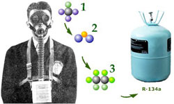
Improving the Refrigerant
Early refrigerant gases were noxious and potentially dangerous to health. They were soon replaced by improved refrigerants that offered safety and higher efficiency of operation.
Ever since the beginning of the twentieth century industrial chemists had been racing to try and discover improved refrigerants. While the early refrigerants – sulphur dioxide and methyl chloride – did the job, they had to be used with great care.
Methyl chloride could be flammable. And fear of the noxious qualities of early refrigerants was a barrier for some, impeding wider acceptance into the home environment.
Moreover, the early refrigerants were corrosive. Frequent maintenance of all components was required, increasing the cost of ownership to the householder.
The first major breakthrough came with the discovery that a class of gases known as fluorocarbons had excellent qualities as refrigerants. Also they were neither toxic nor especially corrosive. The DuPont company registered the trademark name Freon for this group of gases in 1930, and Freon became a widely used refrigerant for the next seventy years.
Only recently, has the negative effect of fluorocarbons, and their close relatives the chlorinated fluorocarbons (CFCs), on the earth’s ozone layer become known. This concern has stimulated further research to develop ozone friendly refrigerant gases like HC-12a and R-134a.

